VME-CDM: Difference between revisions
Jump to navigation
Jump to search
| Line 84: | Line 84: | ||
reset | reset | ||
</pre> | </pre> | ||
==== Building the linux kernel and userland ==== | |||
AAA | |||
Revision as of 20:08, 8 September 2017
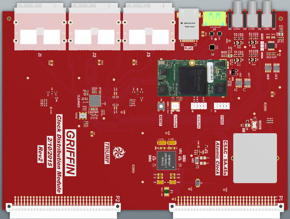
VME-CDM - GRIFFIN Clock Distribution Module
References
- edev login: no public access, sorry!
- edev-pps login: no public access, sorry!
- ladd00 svn login: username: svn, password: svn
- [1] VME-CDM project page on edev.triumf.ca
- [2] Rev2 board schematics (link to edev)
- [3] VME-CDM project page on edev gitlab
- [4] Microsemi ARM processor linux software
General characteristics
Photos
Board schematics
Media:VME_-_Clock_Distribution_Module_Rev2.pdf
Available hardware
- LMK04821 PLL/clock cleaner. Manual: Media:Snas605ar-LMK04821.pdf
- Socket for Atomic clock CSAC Symmetricom CSAC-SA.45s
- Microsemi Smartfusion2 SoC M2S-FG484 (ARM CPU). Product page: https://www.emcraft.com/products/255
- 10/100 Mbit/s ethernet
- no VME interface
- dual mode eSATA connector:
- eSATA clock+sync input or
- USB-A access to ARM CPU serial console via FTDI USB-serial chip
- 24 clock+sync outputs (LVDS) via 6 mini-SAS connectors (SFF-8088)
- 3 dual LEMO connectors: (from top to bottom) ("A" is left, "B" ir right)
- LEMO1A - EXT_SYNC_IN (NIM or TTL sync)
- LEMO1B - EXT_RefClk_IN (NIM or TTL clock)
- LEMO2A - CLOCK_OUT1_NIM (LVDS_CLK7)
- LEMO2B - selected by jumper: CLOCK_OUT2_NIM (LVDS_CLK6) or GPS_1PPS_IN
- LEMO3A - 1PPS_OUT_NIM
- LEMO3B - 10MHz_OUT_NIM
- 4 red and 4 green LEDs
ARM processor
Console connection
- use a USB type-A to type-A cable to connect from CDM eSATA connector to computer USB connector.
- on linux, two /dev/ttyUSB ports will show up (FTDI USB-serial chip)
- use minicom (or other tool) to connect with these serial port settings:
Serial Device      : /dev/ttyUSB2
Bps/Par/Bits       : 115200 8N1
Hardware Flow Control : No
Software Flow Control : No
- type "enter" several times to get the "#" root shell prompt
- on power cycle, observe the output from u-boot and from the linux kernel https://daqshare.triumf.ca/~olchansk/VME-CDM/cdm-boot.txt
- press "enter" or "space" to break into the u-boot command line
- original u-boot settings from Bryerton are here https://daqshare.triumf.ca/~olchansk/VME-CDM/cdm-uboot-printenv.txt
Useful u-boot commands
- reset - reboot the CPU
- printenv - print environment
- saveenv - save environment
- run update - load new firmware image to write it to onboard flash. For it to work:
- IP address settings have to be correct
- tftpd should be configured on the boot server
- developer.uImage should be placed in /var/lib/tftpboot on the boot server
- if successful, the command will print hashes "#" as data is loaded via tftp and finally report successful write to SPI flash
# reboot
### press <enter> many times until you get into the u-boot prompt
run update
reset
- boot linux kernel with DHCP network configuration:
setenv addip setenv bootargs m2s_platform=m2s-fg484-som console=ttyS0,115200 panic=10 ip=dhcp
saveenv
reset
Building the linux kernel and userland
AAA
